Nale Electric is willing to work together with domestic and foreign merchants to create brilliance!


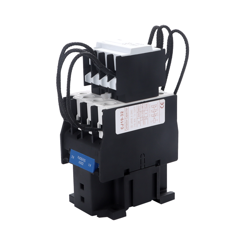
The CHNAILE CJ19 series capacitor switching contactor is designed for power factor correction (PFC) systems in low-voltage distribution panels. This 3-pole contactor handles the switching of capacitive loads with reduced inrush current, supporting panel assemblers in building PFC cabinets that meet utility grid connection requirements.
Manufactured on automated production lines, the CJ19 series incorporates a dual-stage closing mechanism with series damping resistors. This pre-charge design limits the initial inrush current when connecting capacitor banks, a condition that can reach 20 to 30 times the nominal current when standard contactors are used. The contactor complies with IEC 60947-4-1 standards and is available in multiple current ratings to match different kvar capacity requirements.
Industrial clients including switchboard manufacturers, electrical enclosure builders, and power quality solution providers use this contactor for reactive power compensation assemblies. OEM customization options include coil voltage variants, chassis marking, and compliance documentation packages for project-specific requirements.
Parameter | Value |
|---|---|
Product series | CJ19 |
Pole configuration | 3-pole |
Rated operational current (Ie) | 32A |
Corresponding capacitor capacity | 15 kvar |
Rated operational voltage (Ue) | 400V AC |
Control circuit voltage | 220V AC, 50/60Hz |
Inrush current limitation | Pre-charge via damping resistors |
Mechanical durability | ≥ 1,000,000 cycles |
Electrical durability (AC-6b) | ≥ 100,000 cycles |
Operating frequency | Up to 300 operations per hour |
Ambient temperature range | -5°C to +40°C |
Installation method | DIN rail mounting |
Standard compliance | IEC 60947-4-1 |
 |  |
Rated Current (Ie) | Capacitor Capacity (400V) |
|---|---|
25A | 10 kvar |
32A | 15 kvar |
43A | 20 kvar |
63A | 30 kvar |
95A | 45 kvar |
The CJ19 capacitor contactor uses a two-stage contact system to manage capacitive load switching. The first stage connects auxiliary contacts in series with damping resistors, which pre-charges the capacitor bank. This resistor-limited charging phase reduces the initial current spike that occurs when an uncharged capacitor is connected to the supply line.
Within milliseconds, after the pre-charge phase brings the capacitor voltage to a level close to the line voltage, the main power contacts close. At this point, the damping resistor circuit is automatically disconnected, and the main contacts carry the continuous capacitive current. This sequence prevents the thermal stress that would otherwise weld standard contactor contacts under high inrush conditions.
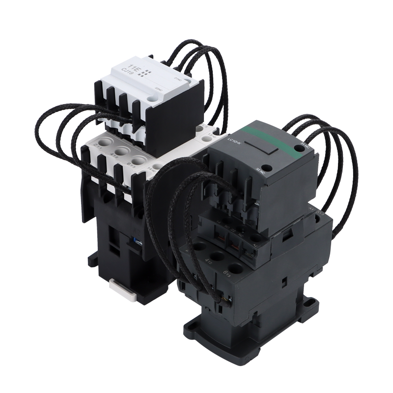
Each pole of the contactor incorporates a dedicated damping resistor assembly mounted on the upper section of the contactor body. These resistors are sized according to the current rating of the specific model, ensuring consistent pre-charge performance across the full product range. The resistor windings are visible as looped black wires connecting the upper auxiliary block to the main terminal system.
The CJ19 series capacitor switching contactor serves as a switching component in automatic and manual power factor correction panels. Common installation environments include:
Low-voltage distribution rooms in commercial buildings
Industrial plant power distribution systems
Solar farm grid connection compensation cabinets
Municipal infrastructure power quality improvement projects
Data center reactive power compensation assemblies
The contactor control coil is compatible with standard power factor controllers and PLC outputs. It operates on command from reactive power regulation systems, which switch capacitor banks in steps to maintain target power factor levels. Panel assemblers can integrate these contactors with most brands of PFC relays and controllers available on the market.
Install the contactor on a standard 35mm DIN rail within a properly rated enclosure. Ensure adequate clearance around the contactor body for heat dissipation, with a minimum of 10mm between adjacent devices. The contactor should be mounted vertically, with the supply terminals at the top and load terminals at the bottom, following the orientation marked on the product label.
Connect the capacitor bank cables to the lower output terminals using copper conductors sized according to the rated current. Tighten terminal screws to the torque value specified on the contactor, typically 1.8 to 2.5 N·m depending on the model. Verify that all three phases are properly connected before energizing the panel, and ensure the capacitor bank discharge time has elapsed before performing any maintenance work.
For panels operating in environments with frequent switching cycles, inspect contact condition every 50,000 operations or annually, whichever comes first. Check for contact wear, loose terminal connections, and proper operation of the damping resistor assembly. Replace the contactor if contact erosion exceeds the manufacturer's specified limit or if mechanical operation shows irregularities.
A standard AC contactor is designed for resistive and inductive loads and does not include inrush current limiting. A capacitor switching contactor incorporates a pre-charge circuit with damping resistors to reduce the high inrush current that occurs when switching capacitive loads. Using a standard contactor for capacitor bank switching will result in premature contact failure due to thermal stress from the 20 to 30 times nominal inrush current.
The CJ19 series is specifically designed and rated for capacitive load switching (utilization category AC-6b). For motor or lighting applications, select a contactor rated for the corresponding utilization category, such as AC-3 for motor circuits or AC-5b for lighting. Using a capacitor contactor outside its rated application may result in performance issues and reduced service life.
Match the contactor rated current to the capacitor bank operating current at the system voltage. As a reference, a 15 kvar capacitor bank at 400V corresponds to approximately 21.7A operating current, and a 32A contactor provides adequate margin. Always verify the actual capacitor current from the capacitor nameplate and ensure the contactor rating exceeds this value.
Standard coil voltages include 220V AC and 380V AC at 50/60Hz. DC coil versions and other voltage ratings are available through OEM customization for volume orders. Consult the manufacturer for specific coil voltage availability and lead times for custom configurations.


