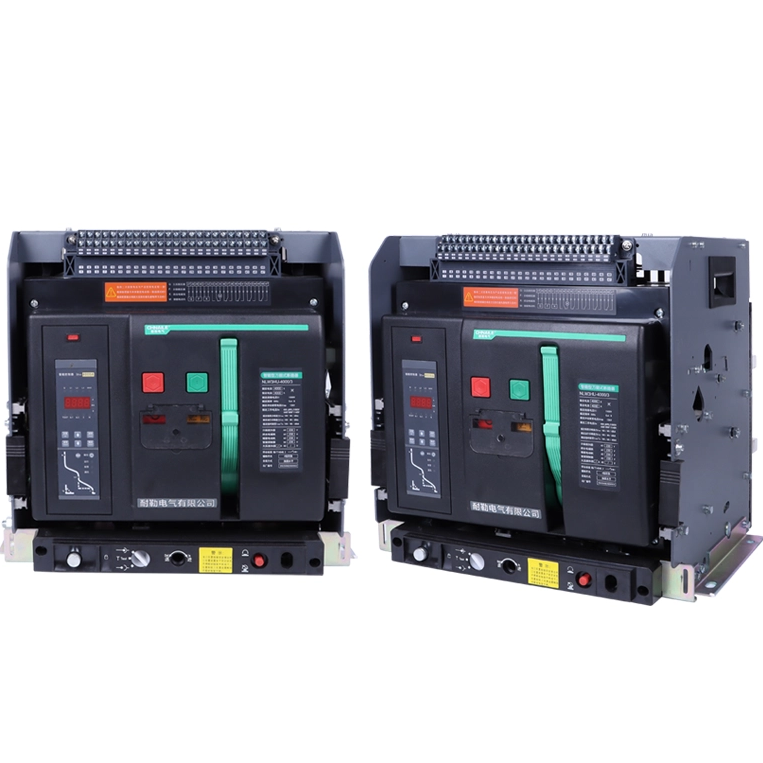
Nale Electric is willing to work together with domestic and foreign merchants to create brilliance!

Views: 0 Author: Site Editor Publish Time: 2026-10-08 Origin: Site
Running legacy electrical infrastructure introduces unacceptable downtime. It also creates severe safety risks. Facility managers face this baseline reality daily. The DW17 Air Circuit Breaker served as a reliable workhorse in industrial power distribution for decades. Heavy usage takes a heavy toll over time. Aging components now present a growing liability. Obsolete mechanical parts degrade rapidly after thousands of cycles. You cannot ignore the threat of an unplanned outage. This guide provides a strictly technical and operational framework. It helps you evaluate a replacement strategy effectively. You will learn how to balance immediate capital expenditure and strict downtime mitigation. We focus heavily on regulatory compliance and system safety. You need actionable engineering insights instead of vendor hype. We will explore direct roll-in retrofits and full switchgear modernization. You must verify critical electrical parameters before deciding. We will show you how to transition safely to modern protection standards.
Evaluate condition over age: Prioritize replacement based on mechanical wear, thermal degradation, and availability of OEM spare parts rather than just years in service.
Choose your upgrade path: Decide between a direct roll-in retrofit (minimizes downtime) and a full switchgear replacement (maximizes lifespan and smart capabilities).
Match critical electrical parameters: Ensure the new unit meets or exceeds the original continuous current ($I_n$) and short-circuit breaking capacity ($I_{cu}/I_{cs}$) of the legacy DW17.
Prioritize modern compliance: Leverage the upgrade to transition from basic thermal-magnetic protection to advanced electronic trip units compliant with IEC 60947-2.
Maintaining obsolete switchgear drains your operational budget heavily. Unplanned outages devastate continuous manufacturing processes. Every emergency intervention requires expensive rushed labor. You must quantify these hidden operational burdens. Relying on an aging electrical backbone threatens facility stability entirely. It compromises baseline safety margins for your staff.
Mechanical degradation destroys reliability over time. Spring-charging mechanisms lose their designed tension. Lubricants dry out and harden inside the operating mechanism. Main contacts experience severe pitting after clearing multiple faults. Arc chutes deteriorate and lose their critical quenching efficiency. Thermal cycling causes micro-fractures in the bus connections. Silver plating on the main contacts wears thin, which increases contact resistance. Higher resistance generates more heat. It creates a dangerous thermal runaway cycle. Thousands of operating cycles weaken every moving part. Visual inspections often miss deep internal wear. You must look beyond basic exterior conditions.
The spare parts bottleneck creates massive system vulnerabilities. Genuine OEM parts disappear from the market entirely. Facility teams often rely on cannibalized components. They purchase untested aftermarket parts to keep operations running. This strategy increases the risk of catastrophic failure. Extended facility downtime becomes inevitable when a rebuilt part fails under load. Your power distribution network deserves guaranteed reliability. Routine maintenance cannot reverse fundamental material fatigue.
Establish clear success criteria for your upcoming upgrade. A successful replacement eliminates unplanned outages completely. It integrates seamless energy monitoring into your existing dashboard. You should expect significantly reduced maintenance intervals. The new system must protect your personnel from arc flash hazards. Define these operational benchmarks before contacting any vendors.
Direct roll-in retrofits utilize a cradle-in-cradle approach. Engineers install a custom cassette into the existing enclosure. Engineers design 3D-modeled copper busbar extensions to bridge the gap. These extensions connect the legacy busbars to the modern breaker terminals. This method significantly reduces operational downtime. You utilize existing busbars and switchboard framing. Installation often takes only a few hours per breaker. However, you face distinct structural compromises. You still rely on aging copper. Existing panel insulation might already show signs of thermal stress. Retrofits do not solve underlying switchboard degradation.
Full switchboard replacement resets the lifespan of the entire assembly. You gain a modernized, high-density footprint. New panels integrate modern safety barriers and optimized cooling. This path maximizes long-term reliability. However, it requires a high initial capital expenditure. You must schedule extensive planned outages. Cabling rework demands substantial labor and coordination. Your facility must accommodate structural changes.
You must deploy a risk-to-constraint matrix to decide your path. Continuous process manufacturing facilities often demand retrofits to avoid week-long shutdowns. Commercial real estate buildings might prefer full replacements during tenant turnovers. Evaluate your specific operational constraints carefully. Precision engineering maintains required electrical clearances in either scenario.
Table: Risk-to-Constraint Decision Matrix
Decision Criteria | Direct Roll-in Retrofit | Full Switchgear Replacement |
|---|---|---|
Downtime Impact | Minimal (4 to 8 hours per unit) | Maximum (Days or weeks required) |
Capital Expenditure | Moderate (Hardware and labor only) | High (New panels, busbars, structural work) |
System Lifespan | Extended by 10-15 years | Completely reset (20-30 years) |
Ideal Application | Continuous process manufacturing | Commercial real estate during renovations |
Matching continuous current limits is absolutely critical. You might upgrade a breaker from 630A to 4000A. You cannot risk thermal overload on existing bus connections. An improperly sized breaker will overheat the legacy copper. The new DW17 Air Circuit Breaker equivalent must align perfectly with your switchboard thermal limits. Never exceed the original busbar capacity without proper engineering calculations.
Short-circuit breaking capacity dictates system safety under fault conditions. Modern facility grid connections often provide higher available fault currents. Your new equipment might require a higher fault-clearing capacity than the original unit provided. Always verify the ultimate breaking capacity and service breaking capacity. The breaker must clear maximum faults without sustaining catastrophic damage. It must remain operational after clearing intermediate faults.
Dimensional verification guarantees a successful installation. Measure phase-to-phase spacing meticulously. Check terminal configurations carefully. Identify whether you have horizontal or vertical busbar connections. Verify absolute depth constraints inside the legacy enclosure. A mismatch of just a few millimeters prevents installation entirely. Physical form factor dictates project feasibility.
Trip unit modernization represents the greatest technical leap. Standard electromechanical trips offer poor accuracy and zero diagnostics. You must move to microprocessor-based electronic trip units. These modern units provide comprehensive LSIG protection parameters:
Long-time delay (L): Protects facility cables and busbars from prolonged thermal overload.
Short-time delay (S): Clears lower-level faults quickly while maintaining system coordination.
Instantaneous (I): Trips immediately during massive short circuits to prevent explosion.
Ground fault (G): Detects hazardous earth leakages to protect equipment and personnel.
Current IEC 60947-2 standards dictate strict performance benchmarks. Evaluate every replacement through this regulatory lens. Local electrical codes demand full compliance for any infrastructure upgrade. Modern breakers undergo rigorous environmental and short-circuit testing. They ensure reliable operation under severe industrial stresses. Adhering to these standards shields your facility from liability.
Modern air circuit breakers drastically reduce incident energy levels. Faster clearing times minimize the destructive force of an arc flash. Many modern units include an Arc Flash Reduction Maintenance System. Technicians activate this mode before opening panel doors. It overrides standard time delays to clear faults instantly. This feature significantly shrinks the required arc flash boundary. It actively protects your maintenance personnel from fatal burns.
Remote monitoring transforms maintenance from reactive to predictive. Onboard communication protocols are no longer optional. Your new breaker must support Modbus, Profibus, or Ethernet/IP. These protocols feed real-time data into your Supervisory Control and Data Acquisition system. Building Management Systems require this data to optimize energy usage. You gain remote monitoring capabilities immediately.
Follow this standardized approach to integrate communications effectively:
Define the specific data points your facility needs to monitor daily.
Select a communication protocol matching your existing BMS architecture.
Map the breaker trip unit registers to your central control software.
Test remote telemetry and alarm triggers before finalizing the commissioning phase.
Pre-installation audits separate successful projects from costly disasters. Never order hardware without conducting a thorough site survey first. Engineers must deploy thermographic imaging on the live equipment. This identifies hidden hot spots on the legacy busbars. Perform strict busbar integrity testing. Verify the existing copper can safely handle a new breaker. If you want to understand proper audit procedures, you can read more about us and our strict engineering methodologies.
Execute a phased rollout strategy to limit operational impact. Do not attempt a massive facility-wide cutover in one day. Schedule individual replacements during regular maintenance windows. Weekend cutovers minimize disruption to core production schedules. A phased approach isolates commissioning risks to a single zone. It provides a safety net if installation issues arise.
Primary and secondary injection testing is absolutely non-negotiable. You must prove the breaker operates correctly before energizing the bus. Primary injection machines push thousands of amps through the main poles. This simulates a real-world short circuit. It verifies the current transformers read accurately. Secondary injection tests the microprocessor logic exclusively. You need both tests to guarantee complete system integrity. Common commissioning failures include reversed control wiring and incorrect trip dial settings. Avoid these mistakes by utilizing certified third-party testing technicians. Document every test result to establish a baseline for future maintenance.
Replacing a legacy ACB is not a simple commodity purchase. It represents a highly strategic infrastructure upgrade. You must balance mechanical realities against modern safety standards. The right upgrade path protects your facility from catastrophic downtime. It transforms an aging liability into a smart, monitored asset.
Shortlist vendors offering comprehensive site audits. Reject suppliers who merely push off-the-shelf hardware. Demand engineered retrofit solutions tailored to your dimensional constraints. Protect your personnel by prioritizing advanced trip units and arc flash mitigation. Schedule a formal electrical system assessment today. Take control of your power distribution reliability.
A: Finding genuine OEM parts is increasingly difficult. Manufacturers routinely phase out legacy production lines. You might find third-party remanufactured parts on the market. Relying on aftermarket spares introduces significant reliability risks. Cannibalized parts often lack rigorous quality control. We strongly recommend upgrading the entire unit rather than risking a catastrophic failure from a faulty rebuilt mechanism.
A: A direct roll-in retrofit takes roughly four to eight hours per breaker. You minimize operational downtime significantly. A full switchboard replacement requires multiple days or even weeks. It involves extensive busbar modifications, cabling rework, and structural changes. Your facility must sustain a prolonged outage to accommodate full replacements safely.
A: Not always. You must evaluate internal structural dependencies first. Minor cradle damage often allows for custom busbar adaptation. Engineers can install a modern cassette inside the existing enclosure. However, severe thermal damage or compromised insulation requires a full switchboard replacement. Always conduct a professional integrity test before deciding your path.
A: Yes, upgrading often lowers your arc flash hazard category. Modern electronic trip units feature faster clearing times. They also include adjustable trip settings and maintenance mode switches. Faster fault clearing drastically reduces incident energy levels. This improves safety boundaries and actively protects your maintenance personnel during live work.