Nale Electric is willing to work together with domestic and foreign merchants to create brilliance!

Views: 0 Author: Site Editor Publish Time: 2026-09-03 Origin: Site
Power distribution relies heavily on a robust first line of defense at the facility level. When immense energy enters your building, you need complete control over its flow and potential faults. As the main incomer breaker for facility switchgear, the air circuit breaker (ACB) serves as the primary line of defense. A mis-specified ACB results in nuisance tripping, severe equipment damage, or catastrophic facility downtime. Selecting the right unit goes beyond matching amperage. It requires balancing fault-clearing capabilities, mechanical form factors, protection unit selectivity, and strict regional compliances. The purpose of this guide is to provide electrical engineers, facility managers, and procurement teams a strict, compliance-aware framework. You will learn the exact steps for optimal equipment sizing in enterprise and industrial Main Distribution Boards (MDBs).
Amperage is only the baseline: Continuous rated current must be evaluated alongside service short-circuit breaking capacity (Ics), which should ideally match the ultimate capacity (Icu) for MDB applications.
Trip units dictate protection precision: Modern ACBs require advanced microprocessor-based trip units featuring LSI or LSIG protection to ensure proper time-current discrimination downstream.
Mechanical configuration impacts downtime: Draw-out (withdrawable) configurations require higher upfront CapEx but drastically reduce Mean Time To Repair (MTTR) compared to fixed types.
Compliance is mandatory: Selection must strictly align with IEC 60947-2 or UL 1066 standards depending on the regional installation requirements.
A power network relies on a strict hierarchy of protective devices. Engineers position the air circuit breaker at the top of this hierarchy. We install it at the immediate secondary side of the main power transformer. This strategic placement ensures it commands the entire downstream electrical topology.
The primary functions of this central unit cover several critical domains. It operates as the core gateway for your facility power.
It carries the total load of the installation safely under normal operational conditions.
It provides the absolute highest level of short-circuit and overcurrent interruption before faults propagate further.
It acts as the primary, highly visible isolation point for facility-wide maintenance and safety lockouts.
Top-tier reliability is completely non-negotiable at this tier. A failure at the MDB level instantly compromises the entire downstream electrical network. When a fault occurs, this device must isolate the problem swiftly. If it fails, upstream utility transformers face massive thermal stress. Catastrophic fires often follow poorly specified incomers. Therefore, precision engineering dictates every choice we make regarding this equipment.
Correct sizing begins with a thorough analysis of steady-state and fault-state electrical parameters. The foundation relies on calculating the continuous rated current (In).
You must size this parameter based on the transformer’s secondary full-load current (FLA). However, calculating FLA alone is never sufficient. Enclosures trap heat. The ambient temperature inside the panel board significantly degrades carrying capacity. Manufacturers provide derating tables for this exact reason. You must apply these derating factors rigorously. Best practice dictates adding a 20 to 25 percent margin above your calculated peak load. This margin accommodates future load expansion securely.
Next, evaluate the short-circuit breaking capacity. This determines how much fault energy the device can safely clear. We split this parameter into two distinct ratings: Icu and Ics.
Icu (Ultimate Short-Circuit Breaking Capacity): This represents the absolute maximum fault current the device can interrupt once. After clearing an Icu-level fault, it may no longer function safely.
Ics (Service Short-Circuit Breaking Capacity): This represents the maximum fault current it can interrupt while remaining fully functional. After an Ics-level fault, you can reset the device and resume operations immediately.
A common mistake involves selecting a unit where Ics equals only 50 percent of Icu. For MDB installations, specifying an Ics equal to 100 percent of Icu is a mandatory best practice. This rule prevents replacing the entire breaker after a major fault event.
Finally, we assess the Short-Time Withstand Current (Icw). This parameter defines the ability to remain closed during a severe fault for a specific duration. This duration typically spans one to three seconds. High Icw values are critical for achieving time-based selectivity. A high Icw allows downstream breakers to trip first, isolating localized faults without shutting down the whole building.
Table 1: Circuit Breaker Fault Current Ratings Explained
Parameter | Definition | Operational Implication Post-Fault | Ideal Sizing Rule for MDBs |
|---|---|---|---|
Icu | Maximum ultimate interruption capability. | Device may require complete replacement. | Must exceed maximum prospective fault current. |
Ics | Maximum service interruption capability. | Device remains fully operable and safe. | Should equal 100% of the Icu rating. |
Icw | Maximum withstand current over a time delay. | Device endures thermal stress without opening. | Must allow sufficient delay for downstream clearing. |
The mechanical frame physically breaks the circuit, but the trip unit provides the intelligence. Older switchboards relied heavily on thermal-magnetic mechanisms. Today, legacy thermal-magnetic units are entirely insufficient for modern MDB applications. They drift over time. They react poorly to ambient temperature fluctuations. They lack the necessary precision for complex networks.
Modern electrical networks demand microprocessor-based electronic releases. These digital units allow exact time-current curve shaping. You can program them to ignore harmless motor inrush currents while responding instantly to genuine faults.
Engineers categorize these digital protections into LSI and LSIG configurations.
Long-time delay (L): This curve handles standard overload protection. It mimics the thermal heating of cables to prevent slow insulation degradation.
Short-time delay (S): This handles short-circuit protection using an adjustable time delay. It ensures proper selectivity, giving downstream devices a chance to clear localized shorts first.
Instantaneous (I): This handles massive, high-level short-circuit protection. It trips the mechanism instantly to prevent catastrophic arc flash explosions.
Ground fault (G): This detects low-level earth leakage. Such leakage often lacks the magnitude to trigger standard short-circuit protocols. Ground fault protection is absolutely vital for personnel safety and fire prevention.
Modern facilities also integrate deeply into smart grids. Microprocessor trip units now double as power quality meters. When specifying a unit, evaluate its native communication protocols. Standard protocols include Modbus RTU, Profibus, and Ethernet/IP. These connections allow seamless integration into your Building Management System (BMS) or SCADA network. Remote monitoring lets facility teams track load trends and predict maintenance needs accurately.
The physical form factor of the equipment heavily influences future maintenance procedures. Your switchgear design limits your choices here. The primary mechanical decision lies between fixed and draw-out types.
Fixed configurations offer a lower initial cost. They feature a smaller physical footprint. However, they present massive maintenance disadvantages. Servicing a fixed unit requires a complete power-down of the MDB. Technicians must physically unbolt heavy copper busbars to remove the device. This process takes hours and requires specialized labor.
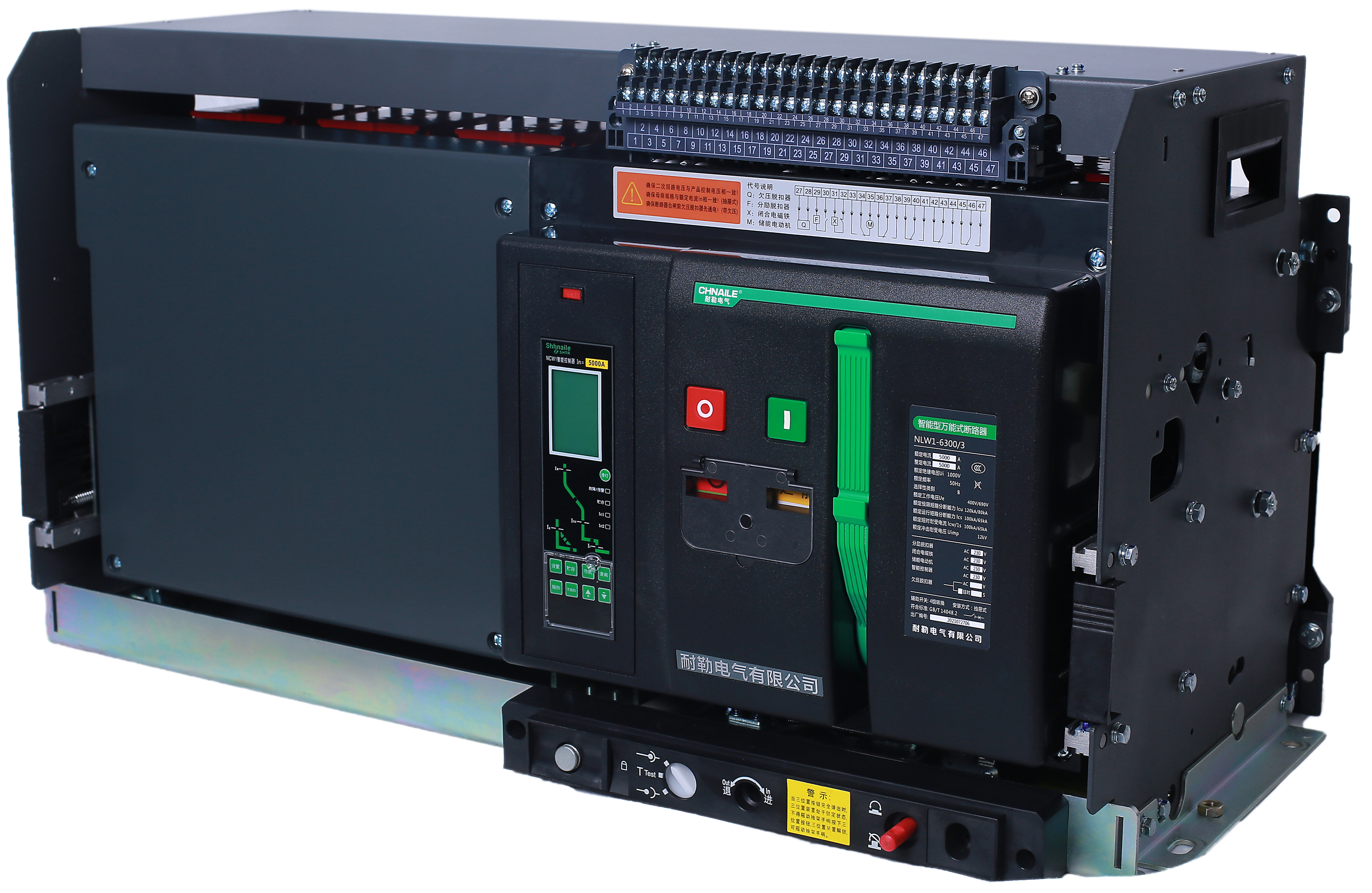
Draw-out, or withdrawable, configurations solve this issue. A draw-out mechanism features a stationary cradle permanently bolted to the busbars. The breaker body itself slides into this cradle. During maintenance, technicians simply crank the body out of the cradle. The framework remains completely intact. Shutters automatically cover the live busbars to protect personnel. We highly recommend draw-out models for continuous-process facilities like data centers and hospitals.
Another crucial mechanical choice is the pole configuration. You must choose between 3-pole and 4-pole designs.
You typically use a 3-pole configuration for standard balanced loads. Industrial motor control centers often utilize 3-pole devices. However, a 4-pole configuration becomes absolutely mandatory under certain conditions. Systems carrying significant unbalanced loads require a switched neutral. Specific grounding topologies, like TN-S or TT systems, demand total isolation during maintenance. Furthermore, generator changeover panels require 4-pole devices to ensure complete neutral separation between utility power and backup power sources.
Mastering ACB selection requires strict adherence to international regulatory frameworks. You cannot install uncertified equipment in critical infrastructure. The geographical location of your facility dictates the governing standard.
For most global installations, IEC 60947-2 serves as the absolute baseline. This standard defines the rigorous testing protocols for low-voltage switchgear components. It establishes the testing methodologies for Icu, Ics, and Icw ratings. If you operate outside North America, your specified equipment must carry full IEC certification.
In contrast, North American installations operate under an entirely different regulatory regime. Facilities in the United States and Canada must comply strictly with UL 1066 and ANSI C37 standards. These standards demand different creepage distances, distinct short-circuit testing parameters, and unique enclosure interlocking rules. An IEC-rated device is rarely acceptable in a UL-mandated jurisdiction.
Always demand verifiable third-party testing certificates from the manufacturer. Self-certification carries high risks. Look for independent laboratory testing from recognized bodies. Institutions like ASTA or KEMA provide unbiased verification of the manufacturer's claims. If a vendor cannot produce an ASTA or KEMA certificate for the specific frame size and interrupting rating you require, immediately discard them from your procurement list. Safety and compliance allow zero compromises.
Proper specification requires aligning rated current, fault-clearing capabilities, trip unit intelligence, and physical form factors with facility demands.
Under-sizing the short-time withstand capabilities leads to poor selectivity, risking total facility blackouts during minor localized faults.
Prioritizing an Ics rating equal to 100 percent of the Icu rating guarantees the device survives severe electrical events without requiring immediate replacement.
Always match the mechanical configuration to your facility's operational uptime requirements, utilizing draw-out frames for critical continuous processes.
As a next step, finalize your single-line diagram, calculate maximum prospective short-circuit currents accurately, and consult a certified manufacturer to validate your final specification.
A: While high-capacity Molded Case Circuit Breakers (MCCBs) reach up to 3200A, an ACB is preferred for main distribution boards. ACBs offer significantly higher short-time withstand currents (Icw). They provide superior maintainability through draw-out chassis designs. Furthermore, they feature highly advanced trip-unit selectivity, which is absolutely required at the main incomer level.
A: It guarantees that if the breaker clears its maximum rated fault current, it remains serviceable. You can safely re-energize the unit without needing immediate replacement. This drastically reduces catastrophic facility downtime and limits emergency procurement scenarios after a severe electrical fault.
A: Depending on environmental conditions and switching frequency, you should perform a visual inspection annually. You must schedule comprehensive testing every 3 to 5 years. Certified technicians should handle contact resistance checks, trip unit secondary injection testing, and mechanical mechanism lubrication during these comprehensive maintenance windows.