Nale Electric is willing to work together with domestic and foreign merchants to create brilliance!


| Quantity: | |
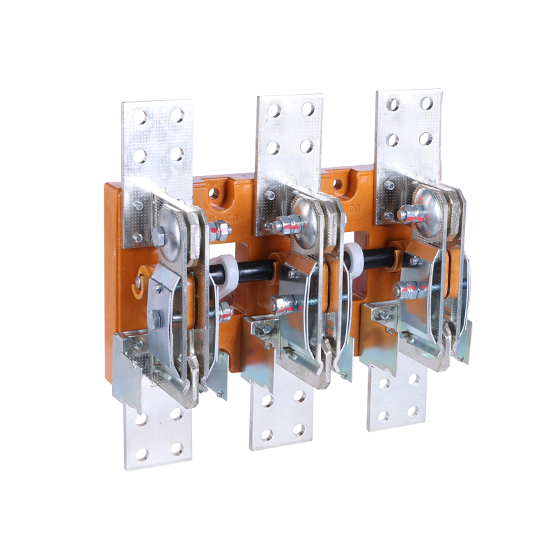
Within the protection and isolation architecture of a low-voltage distribution board, the knife-blade disconnector occupies a legally and technically distinct position from every other switching device in the panel — a distinction whose practical consequence for panel builders, EPC contractors, and government inspection authorities derives directly from IEC 60947-3's definition of isolation function: the creation of a gap between the supply conductors and the downstream equipment that is physically visible to the maintenance technician, measurably sufficient in creepage and clearance distance to withstand the rated impulse voltage, and mechanically stable in the open position without reliance on any spring, solenoid, or electronic latch that could inadvertently return the device to the closed position under vibration, thermal cycling, or control circuit failure. The knife-blade disconnector shown in the product image satisfies this definition through its fundamental operating geometry: when the three blade contacts are withdrawn from their spring-clip receptacles and the assembly reaches the open position, the conducting blades are physically separated from the load-side terminals by an air gap that is directly observable through the open top of the device, satisfying the IEC 60947-3 requirement for "visible isolation" without requiring the installation of auxiliary indicator contacts, position sensors, or transparent covers. This is the characteristic that no moulded-case circuit breaker, no MCB, and no contactor can replicate — the absence of any enclosed mechanism between the open contacts means that the isolation state is self-evident to the maintenance electrician preparing a permit-to-work, and it is this self-evidence that national electrical safety regulations in the Gulf, East Africa, and Latin America reference when mandating a "visible break" isolation device upstream of maintainable LV equipment. For panel builders whose distribution board designs are subject to third-party inspection under local electrical installation codes derived from IEC standards, the presence of a correctly specified knife disconnector at the appropriate point in the protection hierarchy is not a commercial differentiator — it is a code compliance prerequisite whose absence will result in a failed inspection and a costly board modification.
Reading the product image's structural detail from top to bottom provides a precise vocabulary for the device's construction. The uppermost elements are the line-side connection plates — three perforated aluminium plates (one per phase) with a regular grid of circular holes, extending upward from the insulating base to provide the bolted busbar connection interface at the supply side of the disconnector. The perforation pattern serves a thermal management function: the reduced plate mass per unit length accelerates convective heat dissipation from the current-carrying surface, limiting the temperature rise of the connection joint at rated current to within the IEC 60947-3 temperature-rise limit for terminal connections. The silver plating visible on the plate surface addresses the contact-resistance stability requirement at the bolted busbar interface — aluminium oxide, forming spontaneously on unplated aluminium within hours of atmospheric exposure, exhibits a resistivity orders of magnitude higher than the base metal, and its presence at a bolted busbar joint produces a localised resistance increment that manifests as disproportionate heating at the connection point under sustained rated-current loading. Silver plating on the connection plate surface prevents oxide formation at the interface and ensures that the joint resistance remains within the design envelope throughout the disconnector's service life without requiring periodic joint disassembly and re-treatment. The orange insulating base frame — the dimensional and dielectric backbone of the entire assembly — is immediately identifiable in the image as a glass-fibre-reinforced engineering polymer, its colour and surface texture consistent with glass-fibre-filled polyamide 6.6 processed by injection moulding to the close dimensional tolerances required for precise blade-contact alignment across the three poles. The frame's structural role is to maintain the inter-pole spacing at the dimensional value that was established during the device's IEC 60947-3 type testing as the minimum separation necessary to achieve the rated insulation voltage (Ui) and impulse withstand voltage (Uimp) between phases and between phase and earth — tolerances that must be maintained not only at ambient temperature but across the thermal cycling range that the device experiences between no-load and full-load operating conditions.

The blade contact system — the mechanical heart of the knife disconnector's switching function — is visible in the image as three curved conducting arms, each bearing on a spring-clamped receptacle mounted within the insulating base frame, with the spring mechanism providing the contact-closure force that establishes and maintains the low-resistance metallic contact interface in the closed position. The spring clamping mechanism performs a function that is frequently underestimated in the context of an isolation switch: because a knife disconnector is, by definition, not a current-interrupting device (IEC 60947-3 specifies that disconnectors are rated for making and breaking under no-load or load conditions only, not for short-circuit interruption), the quality of the closed-position contact interface — characterised principally by the contact resistance across the blade-to-clip interface — determines the thermal performance of the device under sustained rated-current loading for durations that may extend to months between switching operations in a fixed installation. A spring-clamped contact that maintains consistent contact force across the blade width, despite mechanical vibration, thermal expansion and contraction of the blade and clip materials, and the gradual relaxation of spring pre-load over years of service, produces a contact resistance that remains within the design envelope and a temperature rise at the contact interface that remains within the IEC 60947-3 limit. A contact system where the spring force has been under-specified, or where manufacturing tolerances on the blade thickness and clip geometry produce inconsistent contact force across the contact width, will exhibit elevated and progressively increasing contact resistance — a deterioration mode that is thermally self-reinforcing: higher resistance produces higher local heating, which accelerates spring relaxation, which further reduces contact force, which further elevates resistance, in a positive feedback cycle that eventually produces a thermal event at the contact interface detectable as discolouration of adjacent insulation or anomalous thermal imaging readings during infrared inspection. Our manufacturing process controls the blade thickness and spring clip geometry to tolerances that ensure consistent contact force distribution across the full blade width for every unit produced, with contact resistance verified by four-wire milliohm measurement at the completed assembly stage before the unit is accepted into the shipping lot.
The black insulating crossbar linking the three blade contact arms — visible in the image as a transverse member passing through the lower portion of the blade contact assembly — is the mechanical element that enforces synchronous three-pole operation: when the disconnector handle drives the crossbar, all three blade arms rotate simultaneously to make or break contact with their respective spring-clip receptacles, with a phase-to-phase operating time differential that is determined by the crossbar's dimensional straightness and the uniformity of the pivot bearing clearances at each pole's connection to the crossbar. IEC 60947-3 mandates simultaneous pole operation for multi-pole disconnectors operating in three-phase systems, because sequential pole opening in a live three-phase circuit produces a transient single- or two-phase condition on the load-side network that can generate overvoltages in inductive load circuits and, in the case of a motor load, reverse torque transients that stress mechanical couplings. The crossbar's dimensional specification is therefore not a structural convenience but a protection performance requirement, and it is one of the dimensional parameters verified by our automated optical inspection station during the assembly process.
The commercial argument for sourcing knife disconnectors directly from the manufacturing source, rather than through regional distributors or trading intermediaries, is most clearly expressed through the lens of total cost of ownership rather than unit purchase price. A knife disconnector whose contact spring pre-load has been set to the lower boundary of the acceptable tolerance range — a condition that a distributor-sourced device from a factory operating without calibrated spring-setting tooling may exhibit — will begin exhibiting elevated contact resistance within the first two to three years of service, necessitating either a maintenance intervention (contact cleaning, re-torquing of the blade pivot, or spring replacement) or, in unmonitored installations, an eventual thermal failure that results in an unplanned outage, insurance investigation, and potential structural damage to the adjacent switchboard components. The avoidance cost of that failure event — including the emergency labour, the replacement parts, the panel repair, the insurance claim processing, and the contractual penalty (if any) associated with an unplanned supply interruption — substantially exceeds the unit price difference between a correctly manufactured disconnector and a cost-optimised alternative. Our factory's calibrated assembly process, verified by the milliohm acceptance test described above, is the manufacturing control that prevents the low-contact-force condition from leaving the factory, and it is the control that our quality documentation package — available to OEM customers as part of the supply agreement — demonstrates to procurement engineers conducting supplier due diligence. The platform's configurability addresses the second dimension of procurement cost rationalisation: rated current is scalable across the range from the light-duty isolation positions typical of sub-distribution board incoming isolators through the heavy-duty ratings appropriate for main incomer isolation in large commercial building LV switchboards and municipal substation LV panels, allowing a panel builder to maintain a single qualified supplier relationship across their full disconnector BOM rather than managing separate qualifications for each current tier. Pole count is configurable between the standard 3P configuration shown and a 4P (3P+N) variant for installations where simultaneous neutral isolation is required by the applicable electrical installation code. Insulating base colour — presented in the production-standard orange that provides a visual contrast against the grey panel interior and assists maintenance technicians in identifying the isolation device among other components — is reconfigurable for OEM customers whose panel design conventions, customer brand guidelines, or market-specific colour-coding standards specify a different reference. Contact plating specification — silver plating on the connection plates as standard, with options for heavier silver plating on the blade contact faces for high-cycle isolation duty positions or alternative plating materials for chemically aggressive installation environments — is selectable at the OEM quotation stage. Panel builders, switchgear system integrators, EPC project procurement managers, and utility infrastructure procurement directors who are evaluating this knife disconnector platform for qualification against an active or forthcoming project requirement are encouraged to initiate a direct technical dialogue with our manufacturing team via WhatsApp at +86 15985210820, where our export applications engineering team will engage directly with the rated current, pole configuration, contact specification, volume, and delivery requirements of the specific procurement context.


