Nale Electric is willing to work together with domestic and foreign merchants to create brilliance!


| Quantity: | |
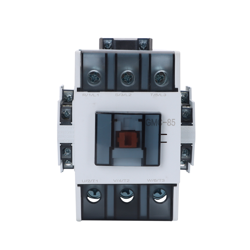
The terminal labelling strategy visible on the GMC-85's line and load faces in the product image — designating each of the six main terminals with a dual reference that simultaneously displays the IEC 60947-1 numerical scheme (1, 3, 5 on the line face; 2, 4, 6 on the load face) alongside the alphabetical motor-winding convention (R, S, T for line; U, V, W for load) and additionally the legacy L1/L2/L3 and T1/T2/T3 format — encodes a specific engineering philosophy about where this contactor will spend its working life and who will wire it, commission it, and maintain it. The IEC numerical scheme (1-2, 3-4, 5-6 through contact pairs) is the reference used by protection relay wiring diagrams, MCC panel wiring schedules, and project electrical documentation produced under IEC 60204-1 (the standard governing electrical equipment of machines) — making it the format that the panel wiring technician consults when assembling the MCC from the wiring schedule, and the format that the commissioning engineer verifies when checking the wiring against the schematic. The alphabetical motor convention (R/S/T input, U/V/W output) is the format used by motor manufacturers on their terminal boxes and in their operating manuals — making it the reference that the site electrician consults when tracing the phase rotation from the motor terminal box back through the power cable to the contactor load face, and the format that a maintenance technician uses when verifying phase sequence during a motor replacement without access to the original wiring schedule. The legacy L1/L2/L3 and T1/T2/T3 designations address a third audience: the installed base of older MCC panels whose original documentation uses this convention (prevalent across pre-2000 installations in the Gulf, East Africa, and parts of Latin America that were wired to the preceding VDE or BS standards), allowing a replacement contactor to be installed by a maintenance technician referencing the original schematic without requiring the schematic to be redrawn to the current IEC numerical convention.
The commercial consequence of this three-layer terminal designation for the switchgear integrator and the panel builder is the elimination of a documentation translation step that would otherwise be required if the replacement or new-installation contactor carried only one of these three convention families. A panel builder wiring an MCC for a commercial building HVAC plant room — where the mechanical contractor's equipment schedule identifies motor terminals in the U/V/W convention, the electrical contractor's wiring schedule uses the IEC 1-2/3-4/5-6 format, and the building management system's motor control documentation references the L1/L2/L3 legacy format — can use a single GMC-85 contactor wiring reference to satisfy all three documentation sources simultaneously, reducing the wiring verification time per contactor position and eliminating the phase-rotation error risk that arises when a technician mentally translates between designation conventions under time pressure. For the MCC assembly workshop producing standardised HVAC motor control panels in volume — assembling twenty or thirty identical panels for a commercial tower development project, where the assembly sequence is repeated by the same team across multiple units — the consistency of the dual-designation terminal format eliminates the cognitive switching error that would arise if different contactor brands in the same panel used different designation conventions for terminals in adjacent positions.
Parameter | Value |
|---|---|
Model | GMC-85 |
Rated Current | 85A |
Rated Voltage | AC 50/60Hz |
Coil Voltage Options | AC/DC multiple choices |
Poles | 3-Pole (3P) |
Insulation Voltage | 690V |
Usage Category | AC-3 |
Mounting | DIN rail or screw fixing |
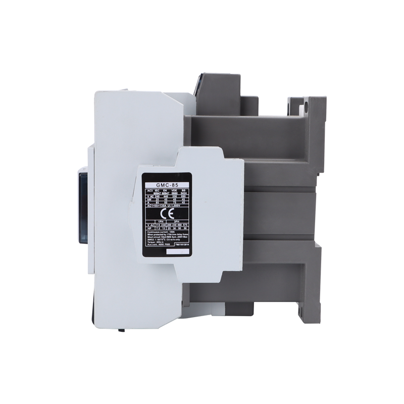 | 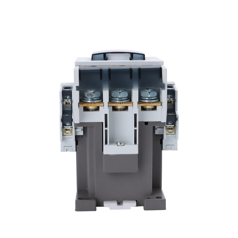 |
The most visually arresting detail of the GMC-85 in the product image — and the characteristic that distinguishes this device most immediately from the smaller NLC1-D40 contactor reviewed in a preceding product page — is the red ferrite coil core that is directly visible through the transparent window panel of the central coil housing, positioned as the geometric centrepiece of the device's front face between the line and load terminal banks. The coil core's visibility is not a design accident or a housing economy measure; it is the product of a deliberate housing geometry decision that allows the panel builder, the commissioning engineer, and the maintenance technician to visually verify, without disassembly, that the coil assembly is physically intact and correctly seated in the magnetic circuit — a verification that is relevant in post-transport inspection (where coil displacement inside the housing can occur without external damage to the housing), in post-fault inspection (where an overloaded coil may exhibit visual signs of thermal distress detectable through the window before an insulation resistance test is performed), and in maintenance scheduling (where the coil's physical condition provides a first-pass assessment of whether the device requires planned replacement before the next maintenance cycle). The red colour of the core — a characteristic of the iron powder or laminated silicon steel composition used for the E-I or U-I magnetic circuit at the 85A frame tier — is visible against the grey interior of the coil housing as a distinctly coloured centrepiece that makes the coil's presence and position confirmable in a single glance, providing the same "at-a-glance health check" function that the green LED on the modular contactor provides for the smaller household format devices, but through a mechanical visibility pathway rather than an electronic indicator pathway.
The electromagnetic physics of the coil assembly at the 85A current tier differ from the coil design of smaller contactors in ways that directly determine the device's application envelope. The coil must generate sufficient magnetic force to drive the armature against the contact spring pre-load — the spring force that holds the contacts open in the de-energised state and that must be overcome on every CLOSE operation — at the minimum coil voltage (typically 85% of nominal, as required by IEC 60947-4-1), while remaining within the coil winding temperature rise limit at maximum voltage (110% of nominal) sustained for the full coil energisation duration. At 85A frame, the main contact spring force is substantially greater than at the 40A frame of the NLC1-D40 — because the contact pressure required to maintain the rated contact resistance at 85A continuous current is proportionally higher, and because the electromagnetic release force required to open the contacts against the spring at the end of a motor running period must overcome the contact welding tendency that higher current makes more probable — and the coil winding must be sized to generate this greater armature force across the full coil voltage tolerance band without exceeding the insulation temperature rating of the coil wire's magnet wire coating. Our coil winding process employs precision-tension winding equipment that maintains consistent wire layering across the full winding depth, ensuring that the coil inductance, resistance, and saturation characteristic match the magnetic circuit design parameters that were used in the device's IEC 60947-4-1 type-test coil performance verification — a production-level consistency requirement that hand-wound coils from uncontrolled production processes cannot satisfy across a batch.
The selection of an 85A frame contactor as the tier at which to standardise a switchgear integrator's or panel builder's heavy-duty motor switching specification is an engineering decision that can be justified through the motor kW coverage that this frame delivers across the three-phase voltage range encountered in the primary target markets. At 400 V three-phase — the IEC standard distribution voltage across the EU, Gulf, East Africa, and South Asia — an 85A frame AC contactor in the AC3 utilisation category covers induction motors in the 37 kW to 45 kW range (at unity power factor and full load efficiency), encompassing the central chiller plant compressor motors, primary air handling unit fans, and large cooling tower pump motors that constitute the highest-power end of a commercial building's HVAC central plant. At 690 V three-phase — used in large MCC assemblies to reduce bus current and cable cross-section at high power concentrations — the 85A frame's AC3 coverage extends to motors in the 55 kW to 75 kW bracket, addressing the large primary pump and refrigeration compressor motors encountered in district cooling plant, large commercial refrigeration facilities, and industrial process cooling systems adjacent to commercial developments. This kW range coverage means that a panel builder whose MCC product range serves both mid-tier commercial HVAC plant (requiring 18.5 kW to 30 kW motor contactors from the smaller NLC1-D40 frame) and upper-tier central plant (requiring 37 kW to 55 kW motor contactors at 400 V) needs precisely two contactor frame sizes to cover the full commercial building motor control spectrum — the 40A frame for the distribution-level motors and the 85A frame for the central plant motors — a two-frame strategy whose vendor qualification, documentation management, and workshop tooling implications are manageable within a single supplier relationship when both frames originate from the same source factory under the same quality management system.
The panel-mount flanges visible projecting from both lower sides of the GMC-85's housing in the product image — flat mounting ears with through-holes for bolted panel fixation — reflect the installation architecture of the 85A frame tier: at this current level, the vibration energy generated by large induction motor starts (the inrush impulse transmitted through the contactor body to its mounting structure during energisation) is sufficient to work loose a DIN rail snap-on mounting over repeated switching cycles, and the bolted flange mounting provides the mechanical retention security that a sub-frame of this weight and the inrush forces it must withstand require for reliable long-term installation. For MCC panel builders whose enclosure design allocates bolted-mounting positions for heavy-frame contactors as a standard MCC cell layout element, the GMC-85's flange geometry — configurable to match the mounting bolt pattern of the specific MCC enclosure standard the panel builder employs — eliminates the need for supplementary mounting brackets or adapter plates that would otherwise add panel assembly labour and the risk of vibration-loosening at the bracket-to-enclosure interface. The coil voltage — supplied as a customer-specified parameter in our OEM production process, covering the AC 220–230 V standard for IEC-format MCC control buses, AC 110 V for legacy North African and Middle Eastern infrastructure standards, AC 380 V for direct-on-main coil energisation in certain Chinese-standard plant configurations, and DC 24 V or DC 48 V for BESS management relay control circuits operating from battery-backed DC buses — is one of the configuration dimensions through which our production process serves a project specification rather than forcing the project specification to adapt to a catalogue constraint. Switchgear integrators, MCC panel builders, commercial HVAC electrical contractors, BESS system integrators, and utility infrastructure procurement managers evaluating the GMC-85 contactor platform for current or forthcoming motor control project requirements are encouraged to initiate a direct technical dialogue with our manufacturing team via WhatsApp at +86 15985210820, where frame current, coil voltage, auxiliary contact complement, mounting configuration, housing colour, and project volume parameters will be addressed by a dedicated export applications engineer returning a complete technical and commercial proposal within one working day.